Solar Powered Air Compressors


Single/Dual Solar Air Compressors
- Completely ELIMINATES natural gas emissions
- Equipped with Six Channel Dump Control Module and Compressor (if needed)
- Modbus communication allows remote reporting of significant events
- Does not require replacement of the level controller or dump valve, and little or no loss in production
Single Solar Air Compressors

Single Solar Compressor
- Eliminates natural gas emissions sourced by instruments at the well site
- Built and tested for dependability. More than 3,600 hours running without any maintenance
- Modbus communication allows remote reporting of all events
- Microcontroller logs and stores system events
- 140 Watt Solar Panel (Expandable)
- Extended run time with two 110 Ah deep cycle batteries (Expandable)
General Specifications:
- Operating Voltage: 12 vdc
- Power Source: Photovoltaic (Typical).
- Options:
- Commercial AC power
- External 12vdc source
- Options:
- Energy Storage: 12 vdc, sealed lead acid batteries (AH capacity to be determined by the application)
- Battery Bank Temperature Range:
- -40 to 60°C (Discharge)
- -20 to 50°C (Charge)
- Electronic Modules (Expandable):
- Battery Charger and Compressor Controller
- Compressor Driver(s)
- Controller - Battery Charger: 20 Amp Maximum Solar Array Current (Expandable)
- Controller - Compressor Drivers: Independent control of up to two (2) air compressors
- Compressor Driver: Soft start, continuous duty 75A max.
- Electronic Mods. Temperature Range: -20 to 70°C
- Air Compressor Standard Duty: 100% Duty Cycle at 100psi and 72°F
- Normal Operating Pressure Output: Compressor - Up to 100psi for pneumatic safety valves (higher pressures available)
- Air Receiver: Stainless Steel
- Water Condensation Removal: Automated Valve
- Standard System Warranty: Parts and labor - one year from installation
SOLAR AIR COMPRESSOR - BLOCK DIAGRAM
Dual Solar Air Compressor
- Eliminates natural gas emissions sourced by instruments at the well site
- Built and tested for dependability. More than 3,600 hours running without any maintenance
- Modbus communication allows remote reporting of all events
- Microcontroller logs and stores system events
- 140 Watt Solar Panel (Expandable)
- Extended run time with two 110 Ah deep cycle batteries (Expandable)
This upgrade represents a vast improvement on the system performance while totally eliminating natural gas emissions
General Specifications:
- Operating Voltage: 12 vdc
- Power Source: Photovoltaic (Typical).
- Options:
- Commercial AC power
- External 12vdc source
- Options:
- Energy Storage: 12 vdc, sealed lead acid batteries (AH capacity to be determined by the application)
- Battery Autonomy: 15 days without solar radiation standard. Other criteria may apply depending on geographical location
- Battery Bank Temperature Range:
- -40 to 60°C (Discharge)
- -20 to 50°C (Charge)
- Electronic Modules (Expandable):
- Battery Charger and Compressor Controller
- Compressor Drivers
- Expandable for additional solar modules
- Controller - Battery Charger: 20 Amp Maximum Solar Array Current (Expandable)
- Controller - Compressor Drivers: Independent control of up to two (2) air compressors
- Compressor Driver: Soft start, continuous duty 45A max.
- Electronic Mods. Temperature Range: -20 to 70°C
- Air Compressor Standard Duty: 100% Duty Cycle at 100psi and 72°F
- Operating Pressure Output: Up to 100psi for pneumatic safety valves - Independent set points for each compressor
- Air Receiver: Twin 9-gallonStainless Steel
- Water Condensation Removal: Automated Valve
- Standard System Warranty: Parts and labor - one year from installation
- Auxiliary Power Connector: Reverse Polarity Protected, 100A Max.
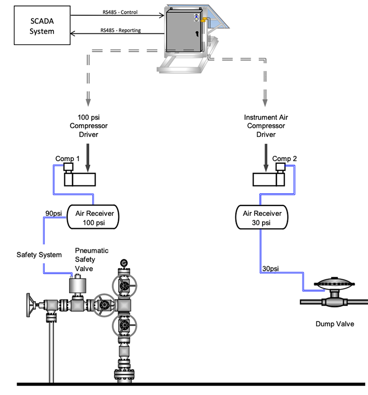
DUAL SOLAR AIR COMPRESSOR - BLOCK DIAGRAM
ZEUS DUAL COMPRESSOR USER’S MANUAL
Programmable Solar Powered Air Compressor
INTRODUCTION
This document addresses operation of the ZEUS with application program version “Charger7P.rgd”. Note that for this version to operate correctly you must first install Axiom OS version 149 or later (see instructions near the end of this document).
⚠WARNING - EXPLOSION HAZARD
ONLY INSTALL THE ZEUS IN AREAS KNOWN TO BE NON-HAZARDOUS
GENERAL OPERATION
Upon power application, the charger unit will immediately begin measuring pressure on compressor #1 & #2 and controlling the compressor drivers output to maintain pressures between the call and off setpoints. It will also begin monitoring battery voltage, solar panel voltage and charging current and controlling battery charging.
ACCESSING MENUS
Charger operation is controlled by employing a series of setpoints using the onboard keyboard and LCD display. In order to access the main menu, press the minus (-) key on the unit’s keyboard. The following menu should appear:
*** SYSTEM MENU *** 1 Display 5 Set Clk 2 Setpts 7 Contrast 3 Logon 8 Show I/O
Pressing the down arrow key from the System menu will show the installed OS version, programs version and time of program installation.
*** VERSIONS NOW *** OS rev 149 (operating system version) Charger7P.rgd (program version) 5/4/2022 4:42:48 PM (when the program was loaded to the controller)
Pressing the up arrow key will return the display to the System Menu.
From the System Menu, pressing the appropriate key will transfer the display to a menu that addresses the specific selection. Below discusses the displays, setpoints and logon/logoff as these are specific to this application.
LOGGING ON/OFF
You will need to log on for some of the operations below so the logon/logoff process is described first. If the main menu indicates ‘3 logon’, then you are not logged on and will be blocked from changing setpoints and some values directly accessible on the displays. To logon, press key ‘3’ from the main menu. You will get the following prompt:
Logon code? =
You will need to type in the correct numeric logon code (factory default is “0”) followed by the ENTER key. The system menu will now be the following:
*** SYSTEM MENU *** 1 Display 5 Set Clk 2 Setpts 7 Contrast 4 Logoff 8 Show I/O
To log off, press key ‘4’ from this menu. Also, if you do not alter a setpoint for 30 minutes, the system will automatically log off.
SETPOINTS
Note: Setpoints are system parameters that typically remain constant and are not normally altered in the field. Values that are typically field-application specific are found under the Display menu.
From the System menu, pressing key “2”, will bring up the setpoint menu. Be sure to log on if you wish to change any setpoints. The setpoints in this system and the default values are as follows:
Coul eff(0 to 1.0)= 0.85 Batt capacity, AHr=200.0 Compr1CyclesToDrain=50.0 Compr1DrainSec=1.0 Compr2CyclesToDrain=50.0 Compr2DrainSec=1.0 Drain holdoff tempF=45. Drain restore, Hr:6. Dump OFF delay Sec=30. Level Steady Sec=5. Max address to poll=0. Sol 1 Off delay sec=3. Sol 1 On delay sec =3. Sol 2 Off delay sec=3. Sol 2 On delay sec =3. Sol 3 Off delay sec=3. Sol 3 On delay sec =3. Sol 4 Off delay sec=3. Sol 4 On delay sec =3. Sol 5 Off delay sec=3. Sol 5 On delay sec =3. Sol 6 Off delay sec=3. Sol 6 On delay sec =3. BatV (12 or 24)= 12. Slave Address= 1. TempF now=68.0 (see description below before changing) Logon code:0
When you press key ‘2’ from the main menu, you will be presented with the first setpoint in the list as shown below:
*** SETPOINT *** Coul eff (0 to 1.0)= 0.85 Hit CLR to change...
To move to the next setpoint in the list, press the down arrow or the ENTER key. If you wish to change this setpoint, press the CLR key and the “Hit CLR to change...” line will blank out and you may begin typing a new value. Your entry will appear on that line. Press ENTER after your entry to install the new value.
HOW THE SETPOINTS ARE USED
The setpoints are used as follows in this application:
- Coul eff: The ratio between the energy removed from a battery during discharge compared with the energy used during charging to restore the original capacity. This is used in the calculation of remaining charge. Default is 0.85
- Batt capacity, AHr: sets the assumed battery capacity for calculations of remaining charge. Note: for 24V systems, the value entered should be half of the 12V cumulative battery ratings since the batteries are installed in series pairs.
- Compr 1 Cycles To Drain: this sets the number of cycles between tank water dumps for tank 1.
- Compr 1 Drain Sec: this sets the duration of each dumping cycle for tank 1.
- Compr 2 Cycles To Drain: this sets the number of cycles between water dumps for tank 2.
- Compr 2 Drain Sec: this sets the duration of each dumping cycle for tank 2.
- Drain holdoff tempF: temperature below which drain cycles are paused. This is to prevent attempted operation during freezing temperatures.
- Drain restore, Hr: time after temperature rises above “Drain holdoff tempF” before drain cycles are resumed.
- Dump OFF delay Sec: when using the ZEUS to control a tank dump valve, this controls the amount of time the valve dumps in response to a float “high level” signal.
- Level Steady Sec: when using the ZEUS to control a tank dump valve, this is used to filter false “high level” signals due to tank sloshing. The controller will ignore “high level” signals that are shorter in duration than the value entered.
- Max address to poll: used only with the auxiliary dump control board – Should be Set to 0
- Sol 1-6 Off delay sec: used only with the auxiliary dump control board – Default values 3
- Sol 1-6 On delay sec: used only with the auxiliary dump control board – Default values 3
- BatV (12 or 24): Specifies 12 or 24 volt compressor, battery configuration and solar panel voltage
- Slave Address: Sets address for MODBUS communication with user’s SCADA system. Note: Controller must be restarted for new address to activate.
- TempF now: sets temperature for temperature transducer calibration. This controls the maximum and minimum charge voltages. To complete the calibration, the new value must be installed under the Housekeeping display (See Housekeeping).
- Logon code: Allows the user to change the logon code.
ACCESSING DISPLAYS
Pressing key “1” from the main menu will open the Displays menu. The following displays are available with this version (7P) of the charger application program:
Summary Charger Compressor #1 Compressor #2 ComprStats Housekeeping Cal pressure XD Station 2 (Not used for the ZEUS Compressor) Station 3 (Not used for the ZEUS Compressor) Station 4 (Not used for the ZEUS Compressor) Station 5 (Not used for the ZEUS Compressor) Dump Fuction
Since the LCD has only four lines, only four lines at a time can be shown. Therefore, when first accessed, the display menu will appear as below showing the first four displays available:
0 Summary 1 Charger 2 Compressor #1 3 Compressor #2
If you press the down arrow or ENTER key, the menu will shift down to present two more display choices as shown below:
0 Compressor #1 1 Compressor #2 2 ComprStats 3 Housekeeping
If you keep pressing the down arrow or ENTER key the display list will rotate until it rotates back to the top of the list. The specific displays will be discussed below.
Some displays will contain keystroke prompts to indicate that pressing one of the numeric keys will result in some action. These are always presented as a numeral followed by a right parenthesis. For example, in the following hypothetical display, keys 1, 3, 4 and 9 will result in the listed actions:
Hypothetical Display 1)Lamp test 3)Setpt A=12.34 4)Setpt B=56.78 9)Alarm ACK
- key 1 will cause the alarm lamps to turn on for 2 seconds
- key 3 will enable you to change setpoint A
- key 4 will enable you to change setpoint B
- key 9 will acknowledge alarms
If you press key 1 or key 9 in the above example, the indicated action will be taken with no change in the display. However, if you press a key associated with a settable value such as key 3 or key 4 in the above example, the display will blank and you will be prompted for a new value. After entering the new value followed by the ENTER key, the new value will take effect and the display will return to normal.
SUMMARY DISPLAY
The summary display provides an overview of unit condition as well as options related to the cyclical operation options. Use the arrow key to display lines 5-12.
*** SUMMARY *** PV=13.5 BV=12.4 PSI#1=96 PSI#2=35 No alarms 1)Lamp test 9)Alarm ACK 2)Cycle mode now=OFF 5)Clr cycle timer 3)Cycle min. = 60 (Default=120) 4)Enable min. = 5 (Default=30) Timer now = 20 Compres. Enable = OFF
PV presents the measured solar panel voltage.
BV presents the measured battery voltage.
PSI #1 displays the measured pressure from compressors #1 in PSI. PSI #2 displays the measured pressure from compressors #2 in PSI.
Line 4 summarizes alarms presently active. If there are no alarms, then ‘No alarms’ will be shown on line 4. If one or more alarms exist then the alarm messages will be shown in rotation once per second on line 4.
The functionality of the last 8 lines are described below.
1)Lamp test: temporarily turns on the indicating lamp outputs shown in the connection diagram. 9)Alarm ACK: clears the alarms shown on line 4 of the Summary Display.
2)Cycle mode now: toggles the cycle mode between “OFF” and “ON”.*
5)Clr cycle timer: resets the cycle timer back to “1”.
3)Cycle min: defines the duration of a cycle in minutes.
4)Enable min: defines how long the compressor is permitted to run during each cycle.
Timer now: shows how many minutes the counter is in to a cycle.
Compres. Enable: shows if the compressor is enabled “ON” or disabled “OFF” by the cycle timer.
*The cycle mode is used if the operator wishes to limit the duration the compressor is allowed to run. One example of this is when the compressor is used for soil reclamation duty. In this example, the runtime could be limited to ensure that the batteries are not depleated during each day’s operation. Another situation where the operator may wish to limit cycle duration is when filling large accumulators. Using the cycle mode, the duty cycle of the compressor can be limited to reduce peak temperatures of the compressor head which will extend compressor life.
CHARGER DISPLAY
The Charger display presents information regarding battery charging and the solar panel output.
*CHARGER* SHNT=OFF Pan V=13.5 I=3.4 Bat V=12.4 I=1.4 No Alarms Shunt ON at BV=14.0 Shunt OFF at BV=13.6 Bat charg %=71.2
On line 1, SHNT=OFF indicates that the shunt is off and battery charging is enabled. If battery terminal voltage exceeds the shunt ON setpoint, then the shunt will be turned on, shorting the panel to ground and prohibiting charging. If battery terminal voltage falls below the shunt OFF setpoint, then the shunt will be turned off allowing the panel to charge the battery.
Lines 2 and 3 present panel and battery voltage and current, respectively. For currents, positive current indicates current from the panel and to the battery. A negative current (battery only) indicates battery discharge current.
Line 4 presents any alarms involving the charger. Possible alarms are:
Low Batt alarm
Low Batt Cutoff ON
Shunt ON at BV=14.0 indicates that at a battery voltage of 14.0 volts or above, the shunt will turn on to suspend charging.
Shunt OFF at BV=13.6 indicates that at a battery voltage of 13.6 volts or below, the shunt will turn off to allow charging. The values shown here to indicate the shunt thresholds after temperature compensation.
Bat charg %=71.2 indicates the calculated state of battery charge as a percentage of amp hour capacity.
COMPRESSOR DISPLAYS
The next two displays present information relating to the two compressors and are identical, except that the header will read “Compressor #2” for the second compressor control.
** COMPRESSOR #1 ** PSI=96 Amps=21.0 1)Call=90 2)Off=97 3)HOA=AUTO NOW=ON 4)Hi alarm PSI=150 (Default=150) 5)Lo alarm PSI=0 (Default=0) 6)Overcurrent A=75 (Default=75) 7)Reset fail now=0 8)PSI now=Xducer#1 9)Max run min. = 60.0 (Default=60) This run min. = 0.0
Line 2 presents pressure in PSI being measured and current in amps being supplied to the compressor.
The next 8 lines present seven setpoints related to compressor #1 that can be altered while viewing the compressor display:
1)Call=90: indicates that the present compressor call setpoint (pressure below which the compressor will be turned on) is presently 90 PSI and pressing key ‘1’ will enable you to change the call pressure. If you press key ‘1’, the display will change to:
Call PSI= =
You may now type in a new value followed by the ENTER key to alter the setpoint. If you do not want to change the setpoint, press the ENTER key to return to the compressor display. Other setpoints that you can change:
2)Off=97: indicates the pressure above which the compressor will be turned off. Press key ‘2’ to change it.
3)HOA=AUTO NOW ON: indicates that pressing key ‘3’ enables you to change the HOA (Hand/Off/Auto) state of control of the compressor and that it is presently set to AUTO and the compressor is presently called (ON). If you press key ‘3’ you will get a prompt:
0=Off, 1=On, 2=Auto =
This indicates that entering a value of 0 will turn off the compressor, a value of 1 will turn on the compressor, and a value of 2 will set the compressor for AUTO operation wherein the measured pressure will govern the on/off call to the compressor.
4)Hi alarm PSI=100: indicates that key ‘4’ allows you to set the pressure high alarm setpoint which is presently set to 150 PSI.
5)Lo alarm PSI=0: indicates that key ‘5’ allows you to set the pressure low alarm setpoint which is presently set to 0 PSI.
6)Overcurrent A=75: indicates that key ‘6’ allows you to set the overcurrent setpoint. If the compressor draws more than this current for more than 10 seconds, the compressor will be shut down for 20 seconds then retried. After 3 tries, the overcurrent alarm will be declared and the compressor held off until manually reset.
7)Reset fail now=0: indicates that compressor overcurrent alarm is 0 (off) and pressing key ‘7’ will clear the alarm if it was on.
8)PSI now=Xducer#1: indicates that the pressure reading used to control the current compressor (#1 or #2) is being taken from transducer #1. Pressing the “8” key switches the reading to the other transducer. This feature is useful when the two tanks are plummed together and it is desired that both compressors share runtime. In that scenario, both compressors would be set to transducer #1 (or transducer #2). This option should only be used if the ouputs of both tanks are teed together upstream of any check valves.
9)Max run min.=60.0: is a user set value that limits how long the specific compressor (1 or 2) is allowed to run before shutting down and initiating an alarm. The purpose of this function is to prevent significant leaks from discharging the battery bank.
This run min. =0.0: shows how long the compressor has currently been continuously running
COMPRESSOR STATISTICS DISPLAY
The compressor statistics display presents total compressor run hours and starts for today (since midnight), for yesterday, and since the last preset event (manual presets). Here’s the display:
*Compressor Stats * 1Hr=125.3 Cyc=1234 (Compr1 Tot run hrs and cycles since preset) 2Hr=45.9 Cyc=343 (Compr2 Tot run hrs and cycles since preset) 9)Preset stats 1)#1 Hr Preset=0 (Default=0) 2)#2 Hr Preset=0 (Default=0) 3)#1 Cy Preset=0 (Default=0) 4)#2 Cy Preset=0 (Default=0) Today: 1Hr=3.88 Cyc=17 2Hr=1.45 Cyc=7 Yesterday: 1Hr=5.52 Cyc=33 2Hr=2.97 Cyc=12
Key [9] installs the four preset values that follow into the time and cycle counters. The specific preset values should be entered beforehand using keys [1] through [4].
HOUSEKEEPING DISPLAY
The housekeeping display is the following:
*** HOUSEKEEPING *** 09/28/2015 21:05:49 TmpF=70.5 C=21.4 Scans/sec=89 Items logged=949 5)=Clear com fails 6)=Dump log nxt=0 7)=Clear log 8)=install tempF cal 9)=install defaults 0)=install PSI defaults
Line 2 presents the present date and time of the realtime clock. It is used to time tag logged data. Line 3 presents onboard temperature in degrees F and C. Temperature is used to temperature
compensate battery charge completion.
Line 4 indicates the processor scan rate in complete program scans per second.
Line 5 indicates number of lines logged. The onboard logger samples an array of data once per
minute and can store 1000 records.
5)=Clear com fails: clears Station 2 – Station 5 communication failure alarms
6)=Dump log nxt=0: indicates that pressing key ‘6’ will send the entire log out the programming
port. The dump has the following form. Each line presents: Date Time, BattV, BattAmps, TempF, Compr#1Amps, Compr#2Amps, Compr#1PSI, ...Compr#2PSI, PanelAmps, PanelV,Bat%Charge
LOG! DUMP 09/28/2012 21:15:38,12.31,-0.15,72.64,4.74,5.09,35.09,0.00,0.00,0.00,0.00
7)=Clear log: pressing key ‘7’ will erase the logged data.
8)=install temp F cal: pressing key ‘8’ will calibrate the temperature transducer to the
tempereature contained in the setpoint list.
9)=install defaults: pressing key ‘9’ will install default values to all setpoints.
0)=install PSI defaults: installs default calibrations for the two pressure transducers and installs
values typical to a 160 psi 0.5-4.5V transducer. These settings can subsequently be overridden by performing the pressure transducer calibrating procedure.
CALIBRATING PRESSURE TRANSDUCER
The display below is the gateway to the pressure calibration procedure. You must be logged on to perform this procedure. This program revision relies on calibration constants stored in flash memory to provide proper offset and span for the transducers. This will be done before the compressors leave the factory, but would need to be repeated if a transducer was replaced in the field. The procedure will start by asking the user to identify which channel they wish to calibrate (for the ZEUS Jr., this will always be channel 1. Then it will ask the user to apply a high pressure to the transducer and type in the pressure that was applied. Usually this will be a pressure near the expected operating point for that channel. The actual pressure you use is not important; only that it is accurately measured and typed in correctly. It will then ask the user to apply a low pressure to the selected channel and then type in the pressure applied. Usually, the air tank would be vented and 0.0 would be entered. Then the user will be asked to press a key to save the calibration. After that, the pressure measurement will be accurate.
*** Press XD Cal *** Key 2=START Must be logged on
If this display is not presented, press key 1 to back up the procedure until it appears. From this display, pressing key 2 will start the procedure and present the following display:
Key 3=toggle channel Channel=1 Key1=Back, Key2=Next
Here, key ‘3’ will toggle between channels 1 and 2. Once the channel to be calibrated is selected, press key ‘2’ to proceed to the next display:
Apply high PSI To channel=1 Then hit key 4 Key1=Back, Key2=Next
Here the user must apply a known high pressure to the transducer and then press key ‘4’. After that a prompt will appear to enter the pressure applied:
High PSI applied= =
Now type in the pressure you applied followed by the ENTER key. The display will transition to the next step:
Apply low PSI To channel=1 Then hit key 5 Key1=Back, Key2=Next
Now apply a known low pressure to the transducer (usually open the transducer to atmospheric pressure) and press key ‘5’. After that a prompt will appear to enter the pressure applied:
Low PSI applied= =
Now type in the pressure you applied followed by the ENTER key. The display will transition to the next step:
Hit key 6 to save New calibration Channel=1 Key1=Back, Key2=Next
Now press key ‘6’ to save the new calibration. End of procedure; the transducer should now accurately measure pressure.
CALIBRATING ONBOARD TEMPERATURE
The onboard temperature measurement is used to offset the battery charge completion voltage so as to neither over-charge nor under-charge the lead acid battery whose terminal voltage is dependent upon temperature. To set the temperature calibration takes two steps:
1) Log on and access the setpoint list (key 2 from the main menu) and use the down arrow to traverse down to the setpoint labeled “TempF now=”. Then press the CLR key and type in the present temperature in degrees F at the site followed by the ENTER key.
2) Press the minus key to exit the setpoint screen and get the main menu. Press key “1” to access the display list and traverse over to access the Housekeeping display. On the Housekeeping display, press key “8”. This will install the temperature that you entered as the present calibration for the temperature channel
DUMP FUNCTION DISPLAY
The dump function display shows the statuses of the separator drain control input and output.
**DUMP FUNCTION** DI2=0 Steady Timer=50 0 Delay Timer 0 0
Line 2 presents the the status of the level switch signal (OFF or ON). When tripped, the DI2 value will change from “0” to “1”.
Line 3 presents the status of the delay timer used to prevent false trips (due to sloshing). The first value show will initially be the delay entered (in tenths of a second) in Setpoints under the Level Steady setting. When the controller receives a signal from the tank level switch, the timer will begin counting down. When the counter reaches “0”, it will call the solenoid driver to initiate the dump function. The second value will change from “0” to “1” to indicate that the call is being made.
Line 4 indicates the status of the solenoid driver output. When the the call is made by the Steady Timer, the first value will change from “0” to the value entered (in tenths of a second) in Setpoints under Dump OFF delay. The second value will change from “0” to “1” to indicate that the solenoid driver is energized. When the Steady Timer call is cancelled, the first value will count down to “0”. When it reaches “0”, the second value will change from “1” to “0” to indicate that the solenoid driver output has been de-energized, ending the dump operation.
ALARM and AUDIO OUTPUTS
The charger has AUDIO, FAIL, OK and STROBE outputs. These are pull to ground outputs capable of sinking up to 100 ma. Whenever a new alarm is detected after no alarms have been present both the AUDIO and FAIL outputs will begin flashing ON/OFF once per second and the OK output will turn off. This will continue even if the alarm condition goes away. To acknowledge the alarm(s), access the Summary display and press key “9”. The flashing will stop and the audible turn off. If an alarm is still present, the FAIL output will stay on and the OK output will stay off. Once the alarms are all corrected, then the FAIL output will turn off and the OK output will turn on. The STROBE output is presently unused.
CHARGER MODBUS INTERFACE
The unit is programmed to respond as a slave to modbus RTU polls on RS485 serial port 4. Port serial parameters are: baud 9600, no parity, 8 bit word, 1 stop bit. Slave address is 1.
The tag list for reading statuses using message types 1 or 2 is the following:
Word1: (Charger local alarms)
Bit 1 Low battery voltage alarm
Bit 2 Low battery cutoff alarm
Bit 3 Compr1ThisRunLongAlarm
Bit 4 Compr2ThisRunLongAlarm
Word2: (Remote 1)
Bit 1 RunLong alarm
Bit 2 Hall fail
Bit 3 RunTooLongWarning
Word3: (Remote 2)
Bit 1 RunLong alarm
Bit 2 Hall fail
Bit 3 RunTooLongWarning
Word4: (Remote 3)
Bit 1 RunLong alarm
Bit 2 Hall fail
Bit 3 RunTooLongWarning
Word5: (Remote 4)
Bit 1 RunLong alarm
Bit2 Hall fail
Bit3 RunTooLongWarning
Word6: (Remote 5)
Bit 1 RunLong alarm
Bit2 Hall fail
Bit3 RunTooLongWarning
Word7: (Remote 6)
Bit 1 RunLong alarm
Bit2 Hall fail
Bit3 RunTooLongWarning
The tag list for data available in response to message type 3 or 4 is the following. All registers are signed integers:
Register 10 Battery voltage *10
Register 11 Panel voltage *10
Register 12 Temperature, deg. F *10
Register 13 Compressor #1 PSI
Register 14 Compressor #2 PSI
Register 15 Compressor #1 total cycles, LS
Register 16 Compressor #1 total cycles, MS (/1000)
Register 17 Compressor #2 total cycles, LS
Register 18 Compressor #2 total cycles, MS (/1000)
Register 19 Compressor #1 cycles so far today (since midnight)
Register 20 Compressor #1 cycles yesterday
Register 21 Compressor #2 cycles so far today (since midnight)
Register 22 Compressor #2 cycles yesterday
Register 23 Compressor #1 total running hours, LS
Register 24 Compressor #1 total running hours, MS (/1000)
Register 25 Compressor #2 total running hours, LS
Register 26 Compressor #2 total running hours, MS (/1000)
Register 27 Compressor #1 running hours so far today *10 (since midnight)
Register 28 Compressor #1 running hours yesterday *10
Register 29 Compressor #2 running hours so far today *10 (since midnight)
Register 30 Compressor #2 running hours yesterday *10
Register 31 Battery percent charge *10
Register 32 Compressor #1 CALL setpoint, PSI
Register 33 Compressor #1 OFF setpoint, PSI
Register 34 Compressor #1 high alarm setpoint, PSI
Register 35 Compressor #1 low alarm setpoint, PSI
Register 36 Compressor #1 over current setpoint, amps
Register 37 Compressor #1 HOA setting (0=off, 1=on, 2=auto)
Register 38 Compressor #2 CALL setpoint, PSI
Register 39 Compressor #2 OFF setpoint, PSI
Register 40 Compressor #2 high alarm setpoint, PSI
Register 41 Compressor #2 low alarm setpoint, PSI
Register 42 Compressor #2 over current setpoint, amps
Register 43 Compressor #2 HOA setting (0=off, 1=on, 2=auto)
Register 44 Compressor #1 overcurrent event count
Register 45 Compressor #2 overcurrent event count
The tag list for writable control bits using message type 5 is the following. These bits are automatically cleared after reception and action has been taken:
Word1:
Coil 1 Reset compressor #1 overcurrent alarm count Coil 2 Reset compressor #2 overcurrent alarm count Coil 3 Reset OnTooLong alarms
Coil 4 Install Compressor 1 call PSI (below)
Coil 4 Install Compressor 1 off PSI (below)
Coil 4 Install Compressor 2 call PSI (below)
Coil 4 Install Compressor 1 off PSI (below)
The tag list for writable control registers using message types 6 or 16 to the charger receive array are the following signed integers:
Register 3 Compressor 1 call PSI
Register 4 Compressor 1 off PSI
Register 5 Compressor 2 call PSI
Register 6 Compressor 2 off PSI